Summary
The goal of the project was to develop a detailed design and an action plan, through performing research on existing electric vehicle systems, developing a procurement plan for electric vehicle components, designing and fabricating custom electric vehicle components, and constructing a hybrid electric vehicle.
Members and Roles
- Eli Yu - Circuit design and electrical system integration
- James Thompson - Mechanical system design and fabrication
- Ke Liu - Microcontroller system and automation
- Lucas Ye - Battery testing and validation
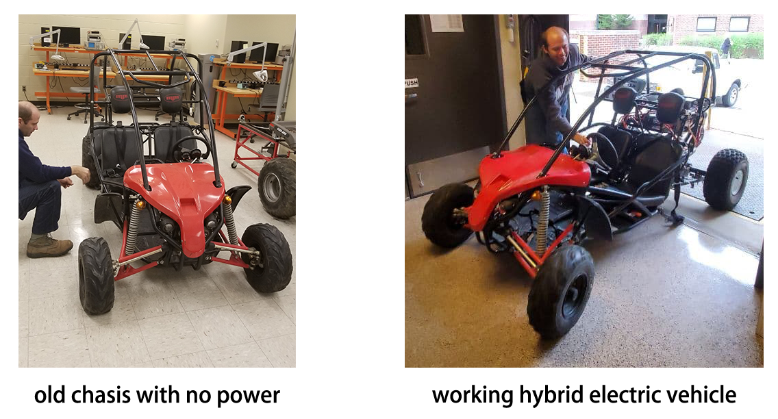
Revival
As the project was based on an old two-seat go-kart chassis for salvage, several salvage operations were required before any new modification.
- The metal parts of the go-kart(mostly the back frame) were de-rusted to maintain structural integrity.
- The flat tires were patched and resealed to prevent leakage after re-inflation.
- The broken brake pedal and brake lines are fixed as the mechanical last resort for all electrical systems failure.
- The hydraulic front brakes are bleeded and refilled with DOT3 brake fluid.
Electrical Design
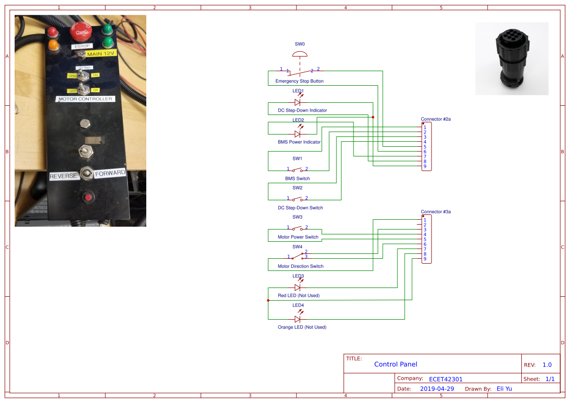
Control Panel
The control panel consists of 1 E-Stop button, 3 two-position switches, 1 three-position switch, and 4 LED indicators(2 of them currently not in used).
From top to bottom, the switches are used to turn on and off the BMS, DC step-down converter, motor controller, and to choose the motor direction. The top right green LED is used to indicate the power status of BMS, and the bottom right green LED is used to indicate the power status of DC step-down converter. The left side red and orange LEDs are not in used.
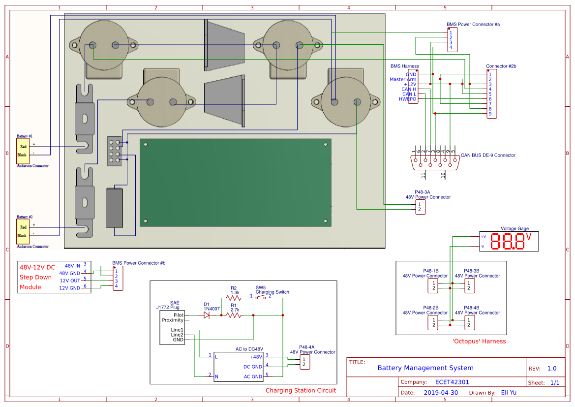
Battery Management System
The BMS is connected to the control panel through Connector #2, and the power exchange between BMS and DC step-down module is through the Power Connector.
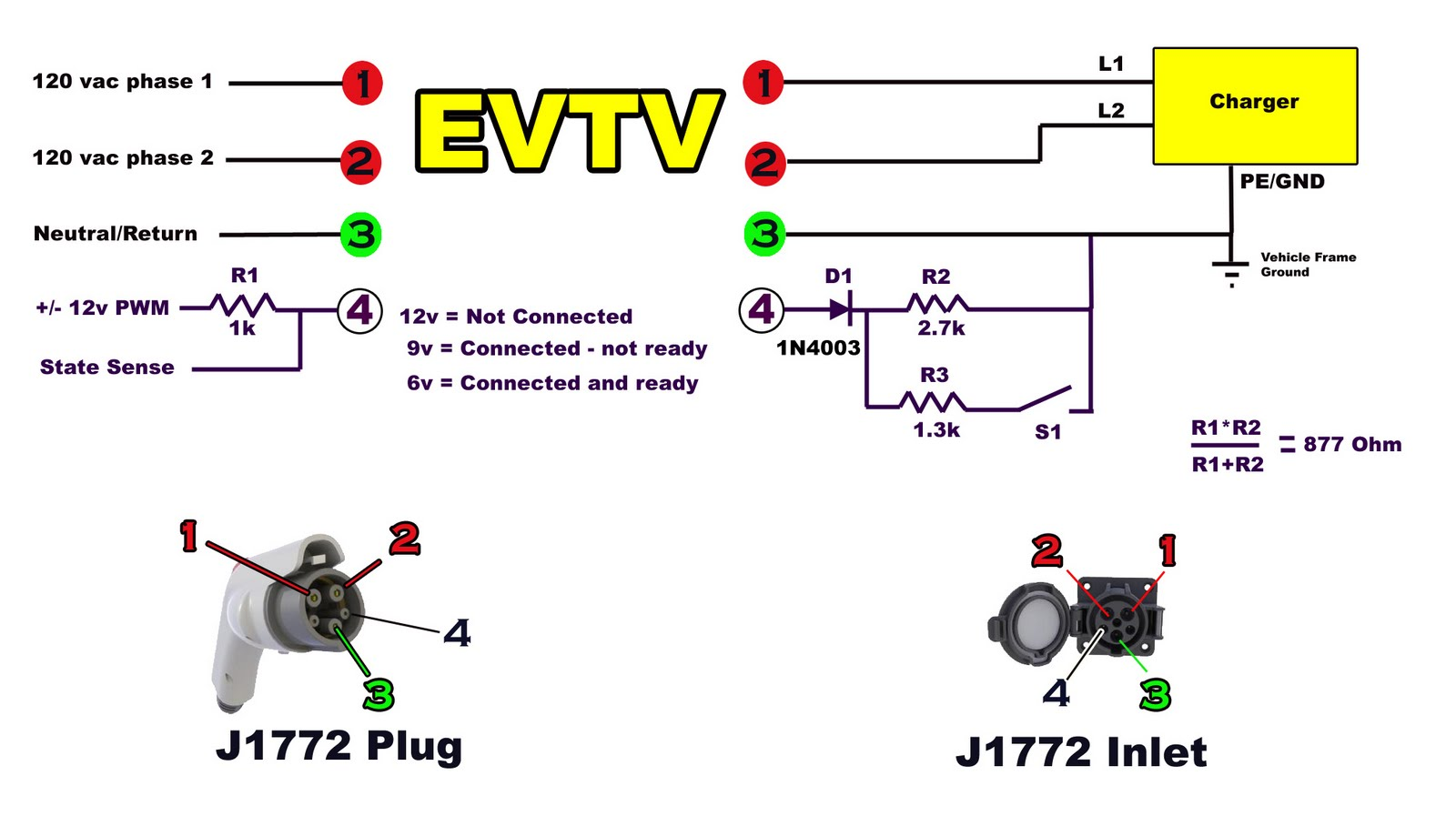
The charging station circuit controls the charging with a single flip-switch, through the pilot signal circuitry and J1772 plug. The AC power from the charging station is then converted into 48V DC power through the AC-DC converter.
The ‘Octopus’ Harness is an acrylic shielded high voltage 48V power bus with 4 anderson connectors connected together with a voltage gage for monitoring. The 4 anderson connectors put together the BMS output, charging station regulated output, gas engine alternator output, and the motor controller power input.
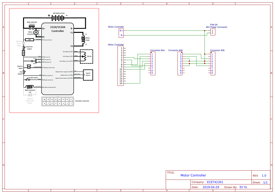
Motor Controller
The motor controller is controlled by the control panel via its connection through Connector #4 and Connector #3.
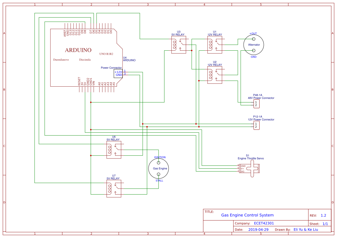
Gas Engine Control System
The gas engine control system is relatively more isolated, while only taking the 48V and 12V power from the rest of the system. More detailed explanation can be found in Microcontroller System.
Mechanical Design
Specs
Gas Engine:
- Features and Specs
- 6.5 HP
- electric start
- low oil safety shut-off
- max RPM: 3400
- output shaft: 3/4 in
- Modifications
- Removal of original key start switch
- Addition of engine start and stop control by the computer
- Addition of a servo controlling the throttle
Alternator
- Features and Specs
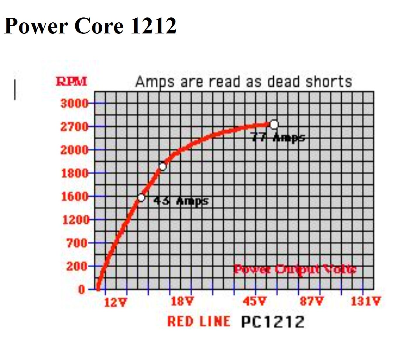
- Power Core 1212 - 48V Permanent Magnet Generator
- based on standard General Motors alternator
- max operating RPM: 1700
- max output power: 77 amps at 50 V
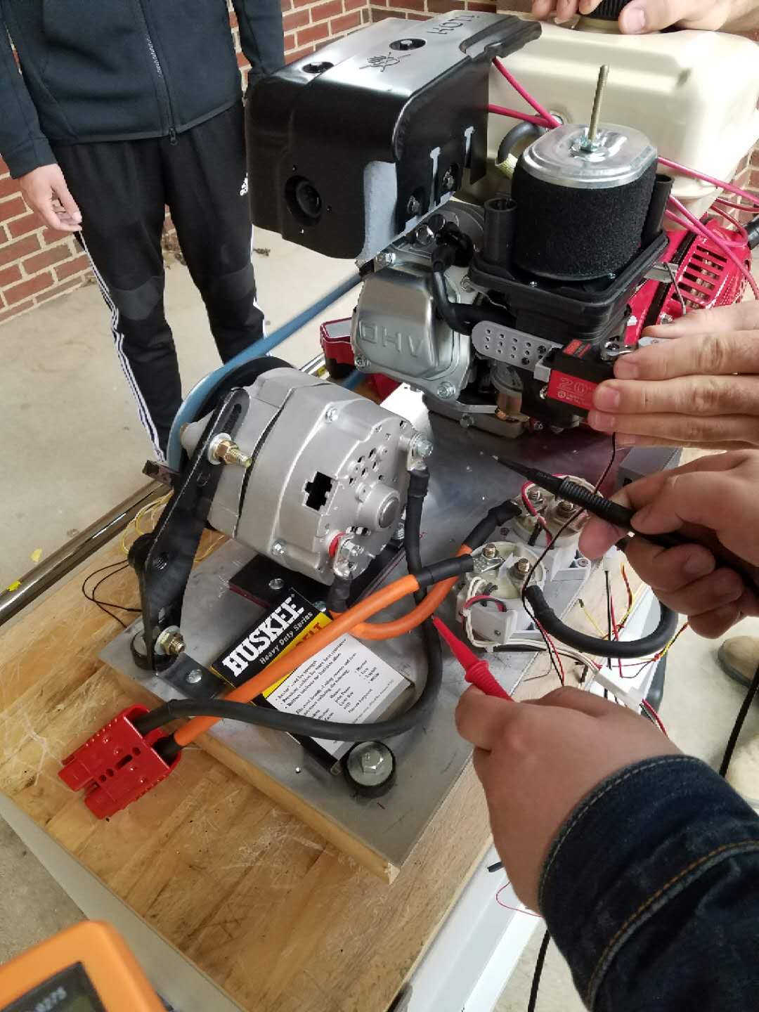
Gunset Assembly
All hybrid power related components are integrated into a single removable package, with the engine and the alternator mounted to a 1/8 inch thick aluminum plate. All engine controlling circuits are also mounted to the plate, including a 5V-12V relay to enable the control of engine starter by computer ,and connected to the rest of the electrical system through connectors. Two relays are utilized to isolate the alternator from the rest of the system while on battery-only mode and when the engine just starts up before reaching the operating speed of alternator to provide sufficient voltage and current. When the relays are closed, the engine-alternator combination would supply power to the rest of the system to either charge the battery with too low voltage level or boost the power output to the motor.
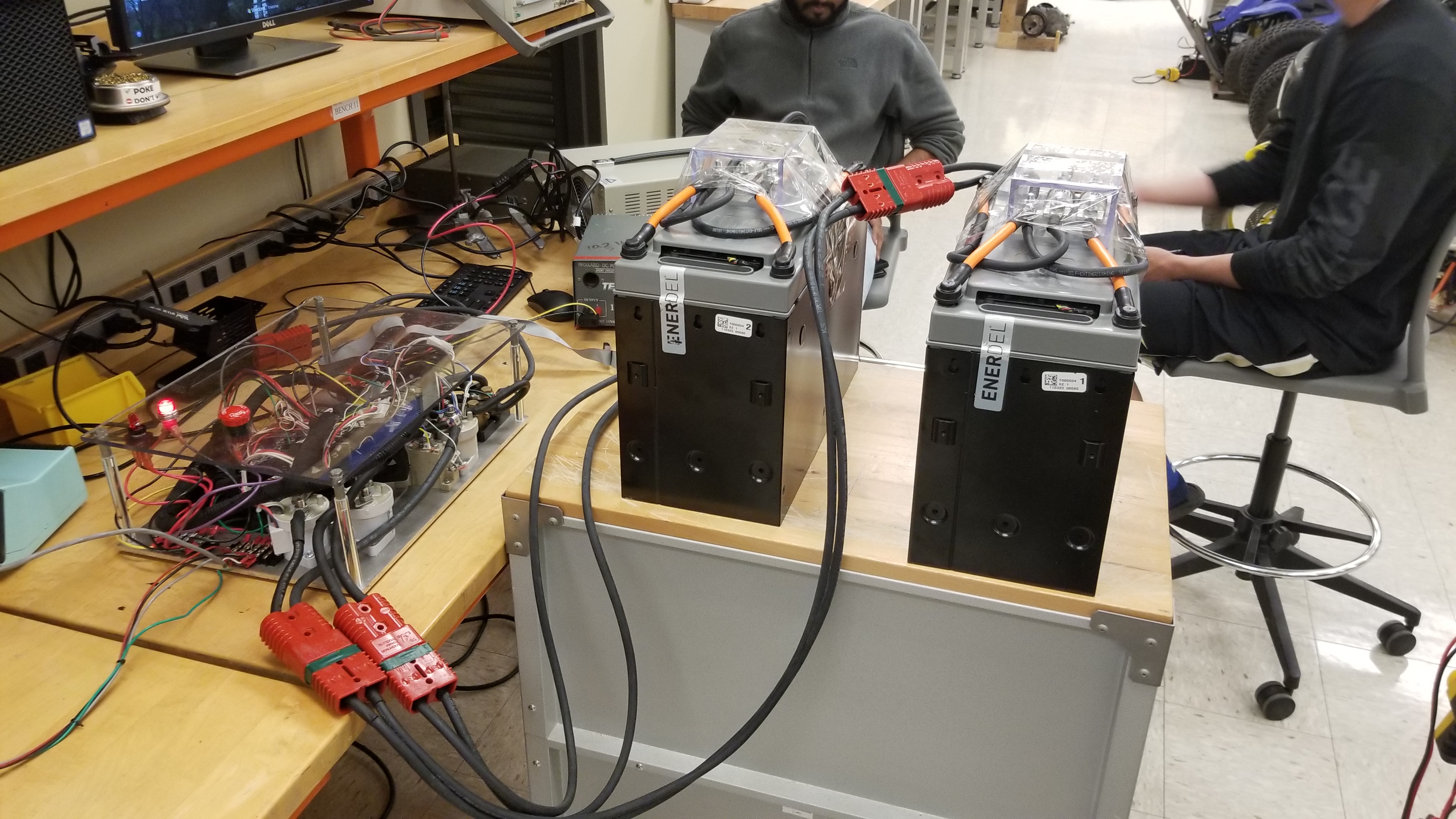
Batteries
Two 48V batteries each with 48 cells are mounted into a specifically welded steel frame and then mounted to the car frame.
Electronics
The BMS circuit is enclosed in a dust-proof plastic box with connectors on the walls. The box is screwed down to the bottom of the rear top car basket frame.
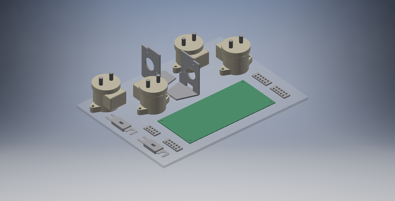
The high power circuits including the Curtis 1510 motor controller, AC-DC converter for charging, 48V-12V DC-DC converter, and the KILOVAC EV200 48V motor controller relays are mounted to a single aluminum plate, and then mounted to the rear bottom car frame.
J1772 Charging Port
The standard J1772 charging plug port is mounted on a 3D-printed plated on the side of the car basket frame behind driver’s seat.
Electric Driving Motor
The electric motor used is EJ4-4001 48-volt DC, shunt-wound, reversible traction motor in a golf cart motor-axle assembly. The motor is capable of providing a maximum of 3.2 HP.
Mechanical Manufacture and Procedures
- replace the original axle frame with fabricated axle frame to fit the golf cart motor-axle assembly
- install 8 in wheel spacers on rear axle to improve stability
- fabricate various mounting panels and brackets
- connect the rear drum brakes on the golf cart axle to the hand brake
- mount throttle rheostat to the underside of cargo basket frame behind driver’s seat and feed throttle wires to the pedal
- mount brake rheostat for regenerative braking to front floor panel and connect to brake pedal
Microcontroller System
CAN Bus Monitor
A Sparkfun arduino CAN Bus shield is used to monitor CAN Bus data flow. Battery voltage data is filtered out to indicate when hybrid system needs to engage.
1
2
3
4
5
6
7
8
9
10
11
12
13
14
15
16
17
18
19
20
21
22
23
24
25
26
27
28
29
30
31
32
33
34
35
36
37
38
39
#include <Canbus.h>
#include <defaults.h>
#include <global.h>
#include <mcp2515.h>
#include <mcp2515_defs.h>
#include <SoftwareSerial.h>

char buffer[456];

//***************************** Setup *****************************

SoftwareSerial mySerial(3,6);   // pin 6 = TX, pin 3 = RX

void setup() {
    mySerial.begin(9600);   // set up LCD serial port for 9600 baud
    delay(500);             // wait for display to boot up
    Serial.begin(9600);     // for debug use
    Serial.println("CAN Read - Testing receival of CAN Bus message");
    delay(1000);

    if(Canbus.init(CANSPEED_500))   // Initialize MCP2515 CAN controller at the specified speed
        Serial.println("CAN Init ok");
    else
        Serial.println("Can't init CAN");

    delay(1000);
}

void loop() {
    tCAN message;

    if(mcp2515_check_message()) {
        Serial.print("check message ");
        if(mcp2515_get_message(&message)) {
            Serial.print("ID: ");
            Serial.print(message.id, HEX);
        }
    }
}
LCD Display
A small LCD display is mounted to the dashboard to display battery voltage, current, and error messages.
1
2
3
4
5
6
7
8
9
10
11
12
void LCD_print() {
    mySerial.write(254);    // move cursor to beginning of first linenos
    mySerial.write(128);

    mySerial.write("                    "); // clear display
    mySerial.write("                    ");

    mySerial.write(254);    // move cursor to beginning of first linenos
    mySerial.write(128);

    mySerial.write("Hello, world!");
}
Gas Engine Control
The ignition and stall of the gas engine are controlled by the microcontroller. Once the ‘ignition’ port of gas engine is connected to 12V, the engine starts. Once the ‘stall’ ported is grounded, the engine stops. Since gas engine and alternator operates at high voltage, a relay is utilized in the control system. The gas engine RPM is controlled by a servo motor to provide desired 48V output.
Code to drive relay
1
2
3
4
5
6
7
8
9
10
11
12
int in1 = 7;
void setup() {
    pinMode(in1, OUTPUT);
    digitalWrite(in1, HIGH);
}

void loop() {
    digitalWrite(in1, LOW);
    delay(3000);
    digitalWrite(in1, HIGH);
    delay(3000);
}
Code to drive servo
1
2
3
4
5
6
7
8
9
10
11
12
13
14
15
#include <Servo.h>

Servo servo_gas;    // Declare Servo

void setup() {
    servo_gas.attach(10);
}

void loop() {
    servo_gas.write(30);    // initial 0 deg
    delay(1500);

    servo_gas.write(150);   // 180 deg
    delay(1500);
}
Testings and Validation
Weight Test
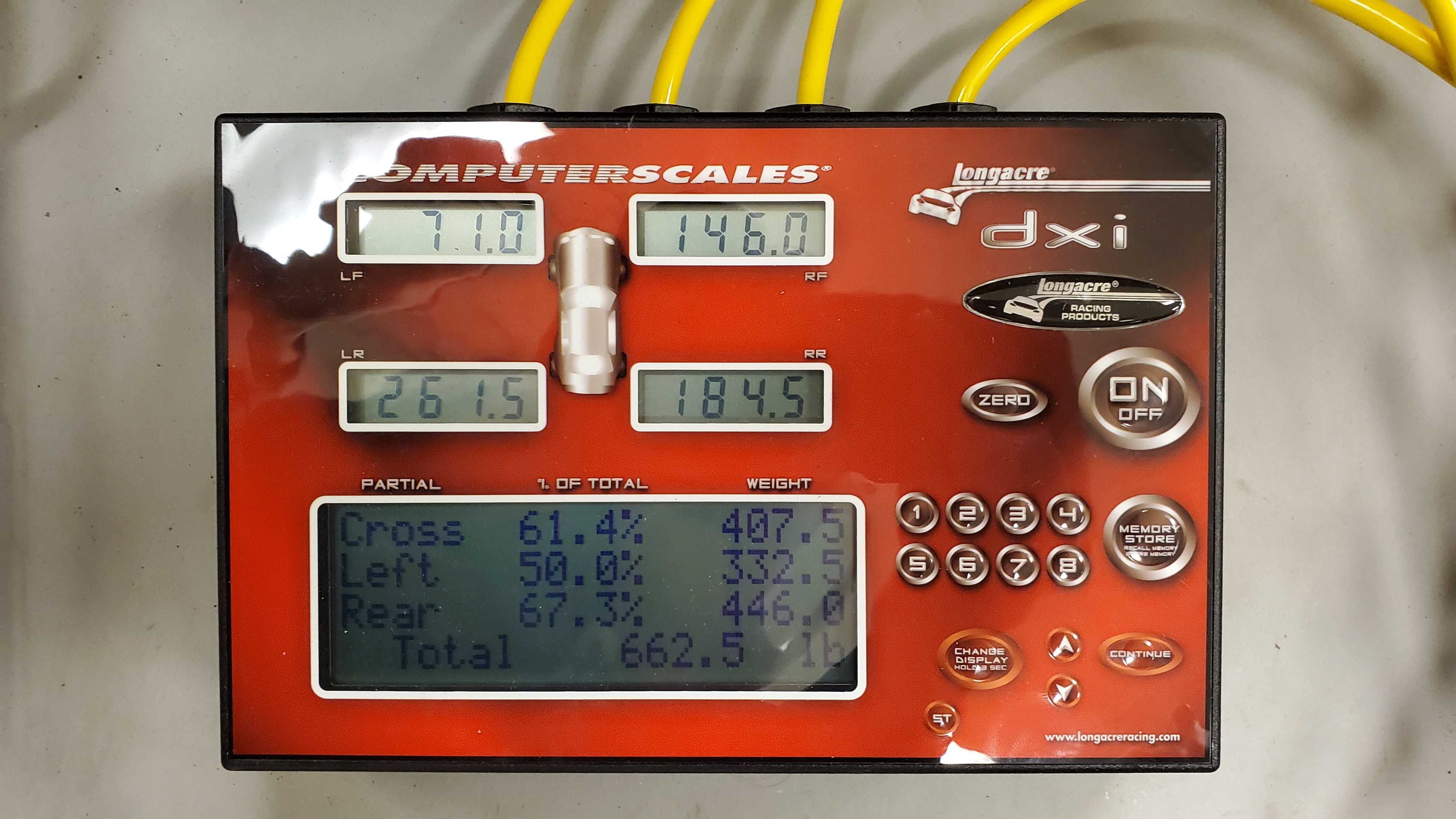
A racing vehicle weight is placed under the wheels to measure the actual weight of the finished vehicle.
Weight Estimation
| quantity | item | weight (lbs.) |
|---|---|---|
| 1 | motor | 35 |
| 1 | alternator | 14 |
| 2 | battery | 140 |
| 1 | frame | 380 |
| 1 | BMS circuit | 20 |
| 1 | electric motor/rear axle assembly | 80 |
| 1 | electronic control board | 30 |
| Total | 699 | |
Test Result
The weight is measured 662.5 lbs, with percentage difference of 5.22% between real case and estimation.
Speed Test
The original golf cart motor-axle assembly has a designed speed of 20 MPH, but considering the increased wheel size on our go-kart of 22 in diameter compared to the gold cart’s 18 in diameter, a 22% increase is expected leading to an estimated max speed of about 25 MPH.
Test Result
The speed test is performed by testing the time taken for the vehicle to pass a certain distance after fully speeded up. During the test, it takes 7.07 seconds to pass 200 ft of distance, which results in the actual speed at 19.3 MPH.
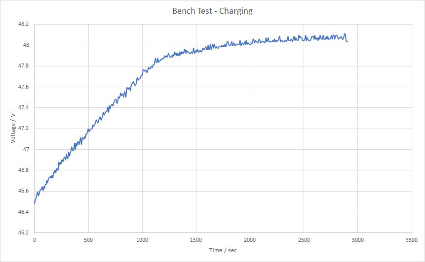
\[\begin{aligned} V = \frac{200 ft \div 5280feet/mile}{7.07 s \div 60 s/min \div 60 min/h} = 19.2876 mph \end{aligned}\]Battery Validation Bench Test
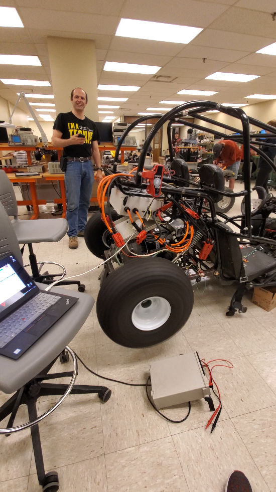
A General Electric electric vehicle charging station is used in lab to test charge the vehicle battery.
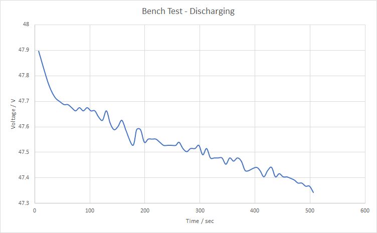
After fully charged, the throttle is held floored to test discharge the vehicle battery.
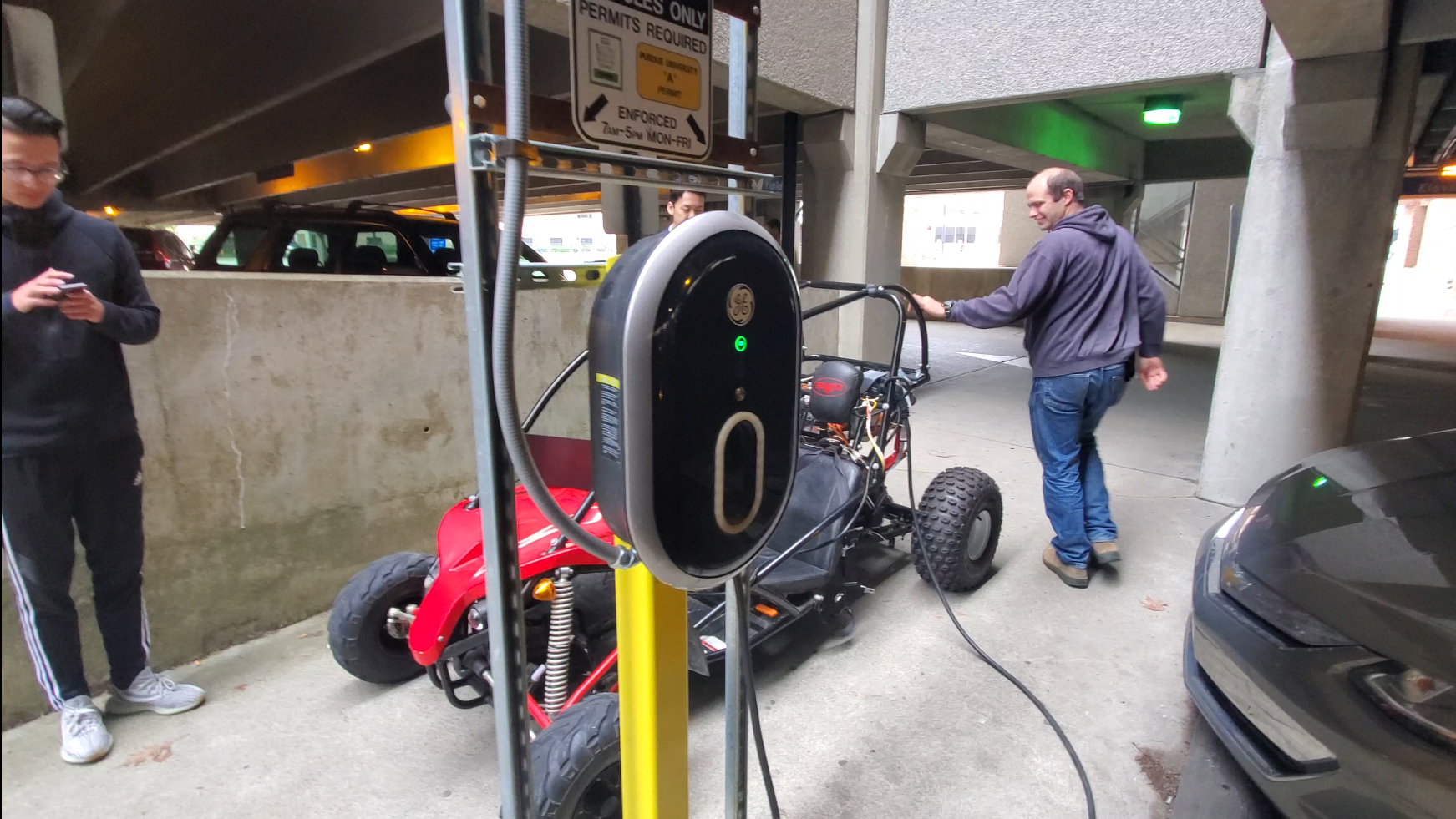
Field Battery Charging Test
The vehicle is driven to a public parking lot, and then tested with a standard GE charging station (with J1772 plug) for commercial electric vehicles. The charging is successful, with a fast charging rate to charge up the battery by 1 full volt from 47 V to 48 V in ~850 seconds (14 minutes).
Drive Cycle Test
The drive cycle test is performed in a public parking lot to simulate typical city driving with flat and sloped roads.
The driving cycle test estimation calculation is done according to the measurement of the parking garage shown below.
The total distance on Flat Surface: 1000.36 m
The total distance on \(3^{\circ}\) Gradient Surface: 338.33 m
The total distance on \(-3^{\circ}\) Gradient Surface: 246.89 m
The speed of the vehicle measured is 19.2876 mph, which is 8.6223 m/s.
Hence, the time taken to travel on different surfaces can be calculated:
Time on Flat Surface: \(\frac{1000.36 m}{8.6223 m/s}=\underline{116.02 s}\)
Time on \(3^{\circ}\) Gradient Surface: \(\frac{338.33 m}{8.6223 m/s}=\underline{39.24 s}\)
Time on \(-3^{\circ}\) Gradient Surface: \(\frac{246.89 m}{8.6223 m/s}=\underline{28.63 s}\)


Thus, through the average power on different surfaces calculated above, the Total Energy Consumed would be:
\[E_{total}=0.71 kW\times 116.02 s + 4.65 kW\times 39.24 s - 3.23 kW \times 28.63 s = \underline{172.37 kJ}\]During actual test, the throttle is released on down slopes, and no energy regeneration, so the actual energy consumption estimation is:
\[E_{total}=0.71 kW\times 116.02 s + 4.65 kW\times 39.24 s = \underline{264.84 kJ}\]In real field test, the voltage of battery goes down through time like below:
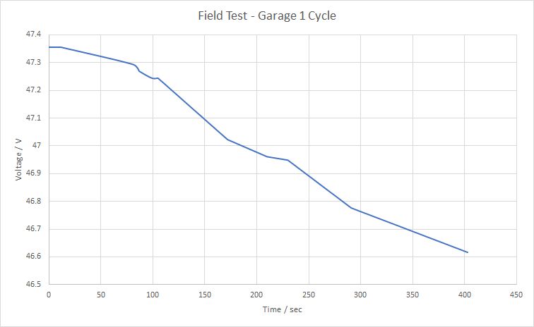
Through the integration of voltage times current over time, the actual energy consumption is 200.403 kJ, which is 24.33% different from theoretical value.