The whole project is sequential, since all functions need to work with the sampling clock for audio signal. The project also uses FSM(Finite State Machine) for I2C interface with the audio codec. On the hardware side, the device itself doesn’t need any accessories, but in order to show its function, an external mp3 player or an electric instrument as well as a speaker is required.
The most challenging part during the developing process is to find out the principles of different audio effects and to figure out how to apply these effects in DSP. Audio delay effects including echo was also researched and figured out, however, it turned out that insufficient internal storage made delay effects only functional with additional memory. Hence, the delay effects are removed from the final version of the project.
There were currently a lot of analog tuners in the market, but mainly have only one effect available. Due to the development of DSP technology, digital tuners would become more and more accessible and affordable. Digital tuners should also be able to apply as many effects as possible compared to the traditional analog tuners. Hence, all these evidence tell a truth that digital tuners would be soon in the market replacing traditional analog tuners.
Operation
Design
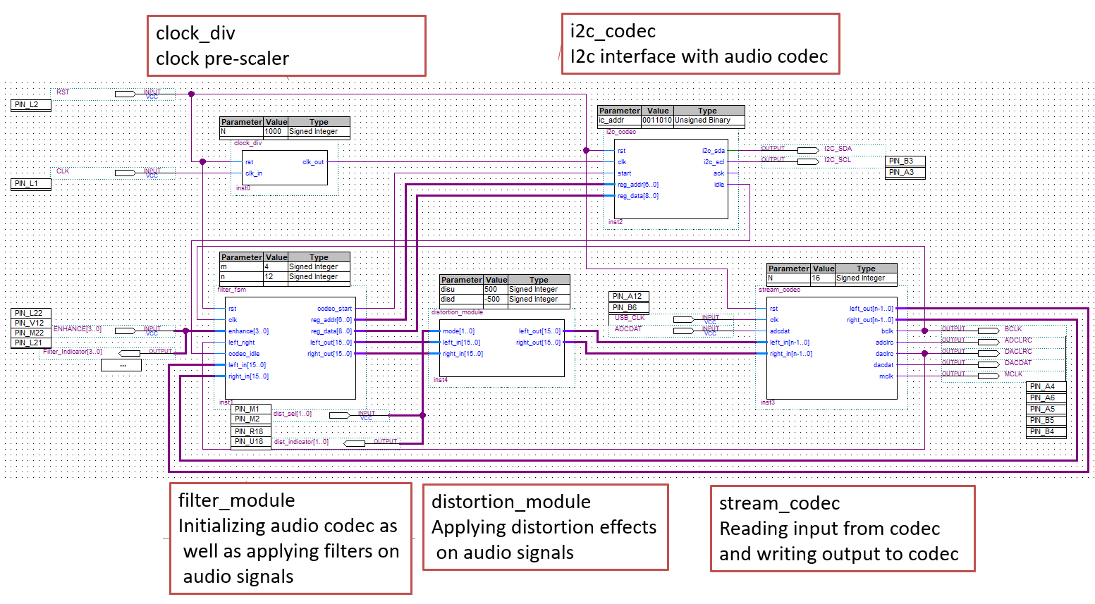
Block Diagram
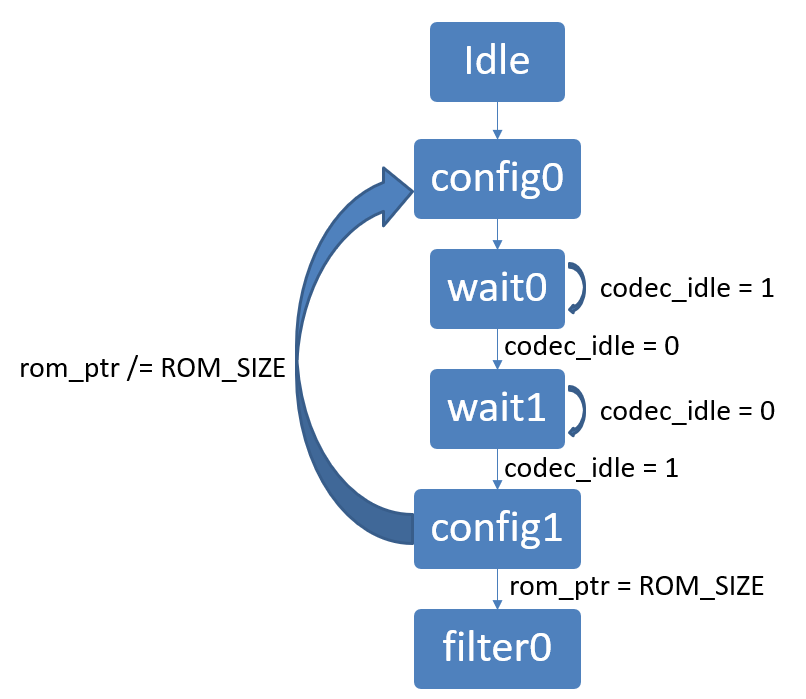
State Machine
PINOUT
The top level entity have following inputs and outputs:
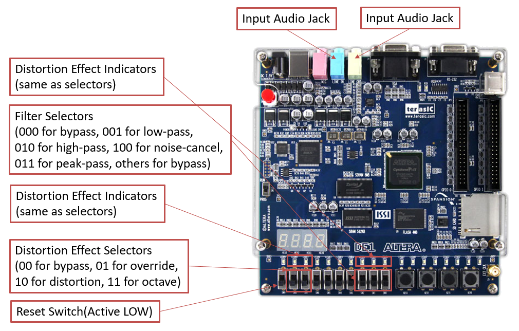
- RST: input of type std_logic – active low. Asynchronous reset. Assigned to SW9.
- CLK: input of type std_logic. 50MHz Clock signal.
- USB_CLK: input of type std_logic. 24MHz Clock Signal.
- ENHANCE: input of type std_logic of length 3. Switch between different filters applied to the audio signal. Assigned to SW2 to SW0.
- Filter_Indicator: output of type std_logic of length 3. Indicating which filter is applied. Assigned to LEDR2 to LEDR0.
- dist_sel: input of type std_logic of length 2. Switch between different distortion effects applied to the audio signal. Assigned to SW8 to SW7.
- dist_indicator: output of type std_logic of length 2. Indicating which distortion effect is applied. Assigned to LEDR8 to LEDR7.
- I2C_SDA: input/output (bidirectional) of type std_logic. SDA (data) line of the I2C bus.
- I2C_SCL: output of type std_logic. SCL (clock) line of the I2C bus.
- ADCDAT: input of type std_logic. CODEC_ADCDAT.
- ADCLRC: output of type std_logic. CODEC_ADCLRCK.
- DACDAT: output of type std_logic. CODEC_DACDAT.
- DACLRC: output of type std_logic. CODEC_DACLRCK.
- BCLK: output of type std_logic. CODEC_BCLK.
- MCLK: output of type std_logic. CODEC_MCLK.
Dilemma - Delay Effects
Audio delay effects including echo was originally part of the project. The delay effects including echo, chorus and reverb, were researched and figured out, however, these effects mostly need a delay of several tens of seconds. This caused the problem of insufficient storage for all these audio data during the delay time. Though I’ve try to decrease the sampling frequency to reduce the amount of data, it turns out to cause a severe loss of audio quality. The only solution I could find is to store the data in a RAM, but it’s too hard to figure out how to read and write RAMs within limited time. Hence, the delay effects are removed from the final version of the project.
Hardware: The hardware used for the project is the Altera DE-1 FPGA Development Board
Software: The code is written in VHDL through Altera Quartus II compiler, download the project code here